Stirling Engines
and Construction Tricks
Links to Hot Air and Stirling Engines
THE HISTORY
The Stirling engine
was invented by Rev. Robert Stirling in 1816.
He was a Scottish
minister. At that time, Stirling engines
were recognized as
a safe engine that could not explode
like steam engines
of that era often did.

Nei motori a ciclo
Stirling il fluido motore (gas) non ha
contatti o scambi
con l'esterno, ma è ermeticamente
confinato all'interno
del motore, quindi non vi sono emissioni
inquinanti. Il ciclo
di funzionamento è molto simile al ciclo
di Carnot, quindi
in questi motori il rendimento approssima
il massimo ottenibile
da un motore termico che funzioni
fra le stesse due
temperature estreme. I motori Stirling
possono funzionare
fra temperature molto vicine:
anche solamente con
7°C di differenza. Sono diventati
interessanti in questi
ultimi anni come possibili motori
puliti ed ecologici
per la conversione diretta dell'energia
raggiante solare.
Il ciclo Stirling inverso ha applicazioni
nei liquefattori di
gas come l'aria e l'azoto.
My friend Adolf Cortel
from Spain shows two models
of Stirling motors
to VIP's at POS2 (Physics on Stage 2002)
in Noordwijk (The
Netherlands).
The motor on the left
is of the kind illustrated
in the following sketch.
THE
STIRLING MOTOR WORKING PRINCIPLE:
The cycle of a generic
Stirling engine is as follows:
Air at the bottom
of the cylinder (E) is heated,
thus expanding and
forcing the piston (A) upward.
At this time the displacer
(B) is driven downward
to the bottom of the
cylinder. Since the displacer
is of a smaller diameter
than the cylinder, the
hot air rushes around
the displacer to the cool
end of the engine
(F). Once in the top end of
the cylinder, the
hot air begins to contract,
sucking the piston
downward. Now the displacer
moves upward, forcing
all the cool air from
the top end of the
cylinder into the bottom end.
Here the air is heated
and the cycle begins again.
Note the 90° phase
shift between the displacer
and the active piston.
Furthermore, this motor runs
completely silent!
SEE
HERE AN ANIMATED STIRLING ENGINE
Thanks to M. Abendschoen
and its web site:
http://michael.abendschoen.bei.t-online.de/hauptmenue.html
YOU
MUST SEE ALSO IMEDIATLY:
http://www.newenergyshop.com
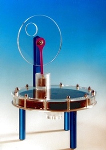
This is the beautiful
Stirling engine from EXERGIA GERMANY
(WWW.EXERGIA.DE)
which incredibly runs on unconcentrated
solar radiation on
its top surface. The same firm sells
also other interesting
engines both in kit and fully assembled.
AN
EXTRAORDINARY STIRLING MOTOR
WITH
THE "RINGBOM" TECHNOLOGY: SEE.
THE TEST TUBE STIRLING MOTOR
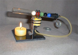
This test tube Stirling
engine is likely the simplest to construct.
It makes an ideal
gift for that budding scientist or engine
enthusiast. Ideal
as science project and teaching aid.
A
BEAUTIFUL SELF EXPLAINING
ANIMATION
Note the 90° phase
shift between the displacer
and the active piston.
Heath is on the left cilynder.
By courtesy of: Steffen
Tschirch, CAD Zeichen Büro
Hildesheimer-Str.
401, 30880 Laatzen
Fax.: 49 5102
914732
http://www.cad-zeichen-buero.com
E-Mail: info@cad-zeichen-buero.com
ANOTHER
INTERESTING
CONFIGURATION
symilar to that of
the above animation:
Owing to the simplified
mechanism of the 90° shifted
displacements of the
pistons, this structure could be
easier to make.
CONSTRUCTION TRICKS AND HINTS
1.
In small engines the connecting rod small end from
the piston or displacer
to the crankshaft may be done by means
of an intermediary
small piece of flexible rubber tubing.
2.
In small engines the piston may be in the form of a thin flexible
rubber membrane, like
in those barely visible in the above photography
of Adolf Cortel from
Spain and in the following image:
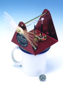
as is used in
the following fine "cofee cup" engine
(sold
also in kit form):
3.
Long life, self lubricating and very low friction pistons are made of
grafite, with the
cylinder made of glass tube. Suitable cylinders
are made by a glass
syringe.
4.
As in the above "cofee cup" model Stirling motor, the bushes and the axle
bearings are suitably
made by teflon. Remember to keep frictions as small
as possible.
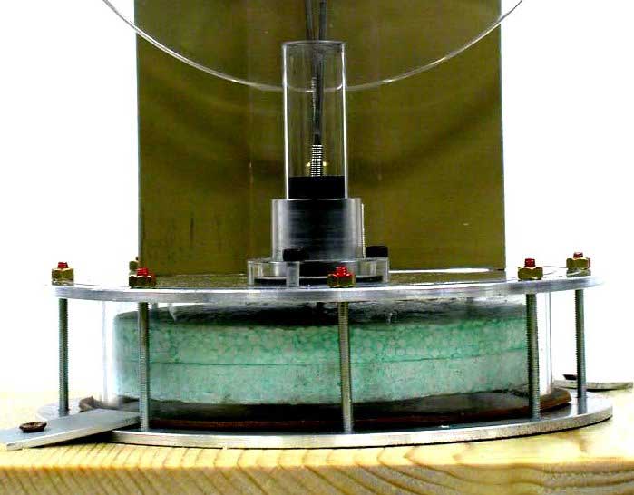
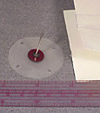
This is a detail of
a Stirling motor constructed in the Laboratory
of
the Museum of Physics of Cagliari University.
Cylinder: glass; piston:
graphite; displacer: styrofoam. Under
a working temperature
difference of 20 °C it turns at 150 rpm.
Note the couplig between
the piston and the connecting
rod made by a spring
of inox harmonic wire.
STIRLING
ENGINE SCHMIDT THEORY
See
the site of Koichi Hirata
See
also the Alan Altman site
for
a calculation program.